Masako Nishimura*1, Rie Nakajima*1, Shinichi Hasegawa*2, Takeshi Sunaoshi*3
When using scanning electron microscopes to obtain high-magnification images of nanometer-scale features, or to observe the outermost surfaces of samples at low accelerating voltages, one frequently finds that the fine surface structure gradually becomes unclear as the observation proceeds, while previously-observed sample regions turn black when the magnification is reduced. This phenomenon, known as contamination, is thought to be due to aggregation and polymerization of residual gaseous hydrocarbon molecules on or near the sample surface due to electron-beam irradiation; these molecules condense and adhere to the sample surface, where they absorb secondary electrons emitted by the sample.
Reducing contamination requires (1) reducing the quantity of hydrocarbon gas molecules that remain inside the sample chamber of the electron microscope, (2) reducing the quantity of gaseous hydrocarbon molecules originating from the sample that adhere to the surface and/or the interior of the sample and sample stub.
More specifically, requirement (1) is fulfilled in most instruments designed to prevent contamination so that the adhesion of remnant gas molecules on the sample surface is restricted to the absolute minimum possible; this includes the use of anti-contamination traps—which adsorb gas molecules on a cooled trapping slab—and oil-free dry vacuum exhaust systems. Nevertheless, to achieve goal (2) it is desirable to pre-process samples before insertion into the electron microscope sample chamber1).
To achieve these goals, we have developed the Zone II for SEM: Tabletop Specimen Cleaner, a device that reduces contamination without damaging the sample by irradiating the sample with ultraviolet light prior to observation to reduce the number of adhered hydrocarbon molecules to the sample surface. In this report, we give an overview of the Zone II for SEM and present examples of its use in actual SEM observations.
Figure 1 shows the Zone II for SEM and Table 1 lists key specifications.
The instrument chassis has dimensions of 300 mm (width) × 262 mm (depth) × 326 mm (height) and weighs approximately 18 kg—a miniaturized, lightweight form factor. Moreover, the instrument requires only a common three-prong (with ground terminal) 100-240 V AC power outlet, eliminating restrictions on where it may be installed.
The instrument can accommodate samples of dimensions up to 100 mm in diameter and 37 mm in height; there is no need to remove the stub from the holder for cleaning. Also, by varying the vacuum pressure in the sample chamber, the ozone volume—which depends on the oxygen concentration—may be varied, and conditions appropriate for particular samples may be programmed and stored.
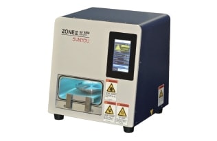
Fig. 1 ZONE II for SEM: Tabletop Specimen Cleaner
| Item | Description |
|---|---|
| UV lamp | Wavelengths: 185 nm, 257 nm, etc. |
| Dimensions | 300 mm (W) × 262 mm (D) × 326 mm (H) |
| Weight | Approximately 18 kg |
| Maximum sample dimensions | 100 mm (transverse), 37 mm (height) |
| Processing modes | UV cleaning mode (offers recipe functionality) Vacuum retention mode |
| Vacuum options | 100 levels of vacuum strength may be selected |
| Processing time options | 1 minute - approximately 24 hours |
| Ozone scrubber | Instrument equipped with catalytic ozone remover |
| Vacuum pump | Diaphragm pump (oil free) |
As shown in Figure 2, the ultraviolet lamp of the Zone II for SEM emits ultraviolet radiation at two wavelengths—185 nm and 254 nm—that are particularly effective for removing hydrocarbons, serving to sever chemical bonds in organic compounds (hydrocarbons). In addition, for sample chambers maintained at relatively low vacuum, the 185 nm component of the ultraviolet light promotes the dissociation of oxygen molecules (O2) into oxygen atoms (O), which subsequently bind with O2 molecules to form ozone (O3); the relevant reaction schema are as follows.
O2 → O + O
O + O2 → O3
The 254 nm component of the ultraviolet light promotes the dissociation of ozone (O3) into activated oxygen atoms (O*) and oxygen molecules (O2) according to the reaction schema
O3 → O* + O2
The activated oxygen atoms produced by the continuous process of ozone formation and dissociation establish chemical reactions with hydrocarbons on the sample surface, which then dissociate into volatile low-molecular-weight molecules such as CO2 and H2O; these detach from the sample surface and are pumped out of the chamber with the vacuum pump.
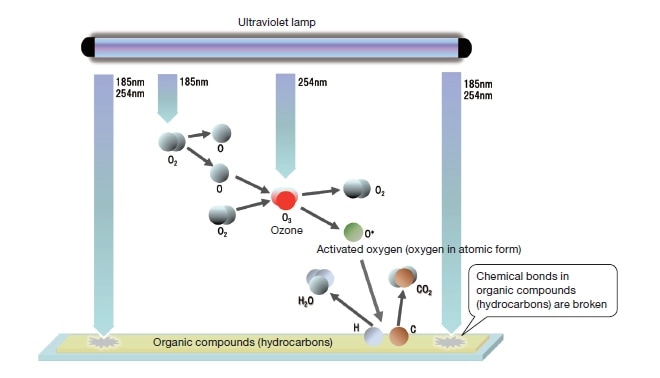
Fig. 2 Principles of sample cleaning via ultraviolet irradiation
Figure 3 shows images of gold particles on a carbon support film; after observation at an accelerating voltage of 30 kV and at 300,000× magnification, observations at a reduced magnification of 100,000× were made to confirm the contamination by electron-beam irradiation. For the sample observed without ultraviolet cleaning [image (a)], the target region is observed with dark contrast due to the adhesion of contaminants. On the other hand, for the sample observed after ultraviolet cleaning of each surface of the support film for four minutes prior to observation [image (b)], no contamination is observed.
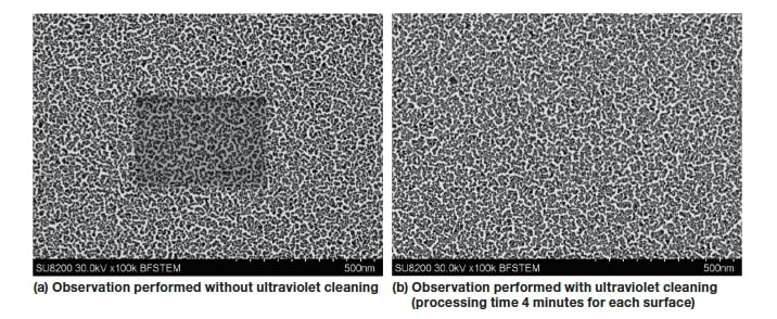
Fig. 3 Observation of gold particles on a carbon support film (accelerating voltage 30 kV, magnification 100,000×).
Figure 4 shows observations, made at a landing voltage of 500 V and at 200,000× magnification, of a sample prepared by dispersing silica particles in an organic solvent, and then spreading this mixture onto aluminum foil. The upper-left inset in each image shows images obtained at lower magnification following the original observation to assess the state of contamination to the sample. For porous materials like silica particles, hydrocarbons from the dispersing medium—which cause contamination—easily become embedded in pores in the sample. For a sample observed without ultraviolet cleaning [image (a)], the adhesion of contaminants fills nanoscale pores of size 20 nm and below, whereupon the structure of the original sample becomes difficult to discern. In contrast, for a sample subjected to 5 minutes of ultraviolet cleaning prior to observation [image (b)], one finds almost no adhesion of contaminants, allowing clear observation of the fine pore structure of the original sample.
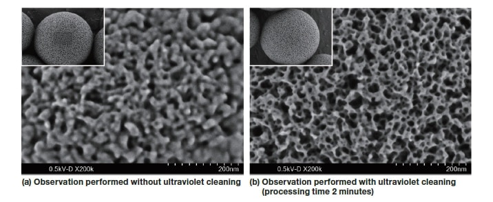
Fig. 4 Observation of silica particles (landing voltage 500 V, magnification 200,000×)
Figure 5 shows results of observations, at a landing voltage of 1 kV and at 150,000× magnification, of an ITO thin film on a glass substrate.
As in Figure 4, the upper-left inset in each figure shows the result of a second observation at lower magnification following the original observation to assess the state of contamination. High-magnification observations of thin-film samples are in high demand, but the large quantity of active substances present in such samples tends to result in adhesion of contaminants. In observations performed without ultraviolet cleaning [image (a)], the structure is unclear due to the contamination; in contrast, observation of a sample subjected to ultraviolet cleaning for 5 minutes prior to observation [image (b)] clearly reveals the fine-grained structure of the sample due to reduced contamination.

Fig. 5 Observation of an ITO thin film on a glass substrate (landing voltage 1 kV, magnification 150,000×)
In this article, the authors gave an overview of the Zone II for SEM: Tabletop Specimen Cleaner and presented examples of observations made with this new tool. By irradiating samples with ultraviolet light at wavelengths of 185 and 254 nm before observations, the Zone II for SEM reduces gaseous hydrocarbon molecules adsorbed on the sample surface through the action of ozone and activated oxygen generated in the irradiation process. This yields an effective technique for mitigating the effects of contamination arising in SEM observations. The Zone II for SEM is useful for high-magnification observation of nanometer-scale features and observations of outermost sample surfaces at relatively low accelerating voltage, allowing clear observation of fine structures characteristic of the sample itself. We expect this tool to find applications in a wide variety of fields, including materials research, semiconductors, and biology.
References
About the authors
*1 Masako Nishimura *1 Rie Nakajima
Application Support Group
Electromagnetic Instruments Department
Science & Medical Systems Service Division
Hitachi High-Tech Fielding Corporation
*2 Shinichi Hasegawa
Tokyo Service Section
Electromagnetic Instruments Department
Science & Medical Systems Service Division
Hitachi High-Tech Fielding Corporation
*3 Takeshi Sunaoshi
Electron Microscopy Applications Group
Application Development Department
Science Systems Product Division
Hitachi High-Tech Corporation
See more
