
Shigeo Mori
Ph.D. (Engineering)
Professor
Materials Structure and Physics Group
Department of Materials Science
Materials Science and Engineering
Graduate School of Engineering
Osaka Prefecture University

Hirofumi Tsukasaki
Ph.D. (Engineering)
Specially Appointed Assistant Professor
Materials Structure and Physics Group
Department of Materials Science
Materials Science and Engineering
Graduate School of Engineering
Osaka Prefecture University
Conventional lithium-ion batteries exhibit outstanding charge-discharge cycle performance and high-energy densities. However, they require electrolytic solutions containing combustible organic solvents, which leads to serious safety hazards. Because of that, the development of all-solid-state batteries, in which electrolytic solutions are replaced by non-combustible inorganic solid electrolytes, have attracted considerable attention. Sulfide-based Li2S–P2S5 glass electrolyte has been used as an inorganic solid electrolyte. Li2S–P2S5 glasses crystallize by heat treatment and their ionic conductivity varies depending on the type of crystal structure that precipitates. A glass ceramic is generally defined as a material obtained by crystallizing glasses. However, the non-crystalline states containing crystallites has not been understood yet. Herein, in this study, the microstructure of Li2S–P2S5 glasses and their relation to ionic conductivity were investigated using transmission electron microscopy (TEM). In addition, we conducted in-situ TEM observation for positive-electrode materials comprising of LiNi1/3Mn1/3Co1/3O2 and Li2S–P2S5 glasses. On the basis of structural changes during heating, the origin of their exothermic reactions was examined.
Research and Development initiatives, targeting solutions to energy resources and environment problems, have attracted considerable attention worldwide. Particularly, the development of safe, long-lasting, and high-capacity batteries is indispensable to develop renewable power sources and environment-friendly electric vehicles. Lithiumion secondary batteries are currently used as power sources for portable devices such as mobile phones and laptop computers owing to their high charge-discharge cycle performance and energy density. In addition, they are also expected to be applied as a large storage battery for electric vehicles and household use by enhancing their size and energy density. However, safety concerns such as fire and explosions exist because they require the use of a flammable organic solvent. To resolve safety risk, all-solid-state batteries, in which electrolytic solution is replaced with a nonflammable inorganic solid electrolyte, has been developed in recent years. Among inorganic solid electrolytes, in particular, sulfide-based solid electrolytes are promising candidates for all-solid-state batteries owing to their high electrochemical stability in a wide potential window and ionic conductivities comparable to that of organic electrolytic solution.
Figure 1 shows the schematic diagram of a bulk-type all-solid-state battery. All-solid-state cells are fabricated by stacking nanoparticle layers. Because a lot of active materials can be introduced into the electrode layer, battery capacity can be significantly improved. For example, the positive-electrode layer consists of a positive-electrode active material and solid electrolytes. Solid electrolyte serves as an ionic conduction path. Thus, in order to realize all-solidstate batteries, it is necessary to develop a solid electrolyte exhibiting high ionic conductivity and an electrode material with a high capacity.
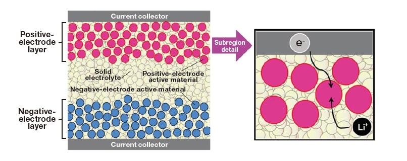
Fig. 1 Schematic diagram of a bulk-type all-solid-state battery.
Sulfide-based solid electrolytes exhibit higher ionic conductivities than oxide-based ones. Furthermore, they are electrochemically stable in a wide potential window. One typical example is the Li2S–P2S5 glass electrolyte. Figure 2 shows ionic conductivity of glasses and glass ceramics in the Li2S–P2S5 binary system. Ionic conductivity of the Li2S–P2S5 glass tends to increase by heating and crystallization1) . Thus, to achieve high ionic conductivity in such a glass electrolyte, it is important to elucidate the morphology and connection of precipitated crystallites in the amorphous matrix. So far, we have conducted high-resolution TEM observations and in-situ TEM observation during heating for Li2S–P2S5 glasses to investigate their non-crystalline states and crystallization behavior2-4) .
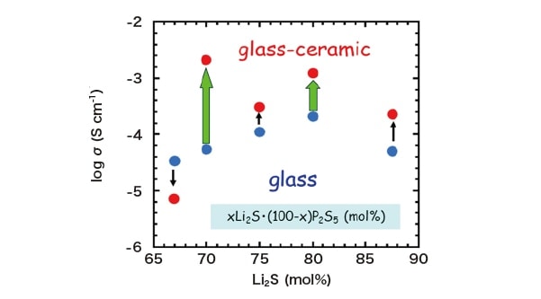
Fig. 2 Ionic conductivity of xLi2S・(100-x)P2S5 (mol%) glasses and glass ceramics1) .
Because sulfide-based solid electrolytes are unstable in air, an inert-gas environment is necessary for their TEM observations. As shown in Figure 3, the samples for TEM observation were prepared in a glovebox filled with inert Ar gas. TEM observations were performed using a vacuum TEM holder and heating TEM holder. To visualize the spatial distribution of crystalline and non-crystalline regions, dark-field (DF) TEM imaging was utilized5,6) . In this imaging technique, a real space image (DF image) can be obtained by using the diffraction spots that appear due to crystallization. Since there is no need to converge the electron beam for taking DF image, sample damage by electron beam irradiation can be minimized. Thus, DF imaging technique can be applied to in-situ TEM observation of crystallization process of glass electrolytes.
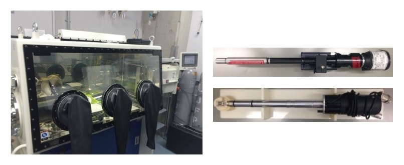
Fig. 3 Experimental setup for TEM observation of sulfide-based solid electrolytes without exposure to air. Left: Glove box. Right: Vacuum TEM holder (upper) and heating TEM holder (lower).
In-situ TEM observations were conducted for the sulfide-based Li2S–P2S5 glasses to investigate the non-crystalline states containing nanocrystallites. The microstructures of 80Li2S・20P2S5 glass-ceramic samples were examined. Their X-ray diffraction data at room temperature was confirmed to be derived from the crystal phase Li3.25P0.95S4, exhibiting high ionic conductivity. Then, in-situ TEM observations were conducted to clarify the morphology and connection of Li3.25P0.95S4 crystallites.
Figure 4 shows a high-resolution TEM image of 80Li2S・20P2S5 glass-ceramic samples. Li3.25P0.95S4 nanocrystallites with a size of 5 nm were present and connected each other in the amorphous matrix, as indicated by the dotted circles. This suggests that the precipitation and connection of Li3.25P0.95S4 nanocrystallites are responsible for high ionic conductivity of the 80Li2S・20P2S5 glass-ceramics.
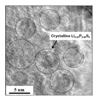
Fig. 4 High-resolution TEM image of 80Li2S・20P2S5 glassceramic sample2) .
Then, the microstructure of the 75Li2S・25P2S5 glasses was investigated. Figure 5 shows the DF images and highresolution TEM image of the 75Li2S・25P2S5 glasses. The electron diffraction (ED) pattern exhibited a halo (inset in the left panel of Figure 5), indicating that the average structure of the 75Li2S・25P2S5 glass was a non-crystalline state. However, bright-contrast regions, indicating the presence of crystalline regions, were clearly observed, as shown in the DF image (left). In the high-resolution TEM image (right), furthermore, nanocrystallites were randomly distributed in the amorphous region, as indicated by dotted circles. That is, the 75Li2S・25P2S5 glasses could be identified as an amorphous state studded with nanocrystallites rather than uniformly non-crystalline state.
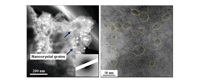
Fig. 5 Dark-field TEM image (left) and high-resolution TEM image (right) of the 75Li2S・25P2S5 glasses2) .
In-situ TEM observation was then conducted to investigate the crystallization process of the glasses. Figure 6 shows the ED patterns of the 75Li2S・25P2S5 glasses, taken at various temperatures. At room temperature, a halo pattern, indicating a non-crystalline state, was observed. Crystallization was detected at approximately 180 °C and, remarkably, proceeded above 200 °C with increasing temperature. Based on the analysis of the ED pattern at 280 °C, precipitated crystalline phase was confirmed to be β-Li3PS4. To better understand the microstructure of the 75Li2S・25P2S5 glass ceramics, furthermore, in-situ TEM observations were performed at 210 °C. Figure 7 shows the DF image (left) and high-resolution TEM image (right) of the 75Li2S・25P2S5 glass-ceramics. The ED pattern in the inset showed the Debye-Scherrer rings comprising of several diffraction spots, while the DF image indicated the spatial distribution of β-Li3PS4 nanocrystallites with a size of approximately 10 nm. β-Li3PS4 nanocrystallites connected each other, as denoted by the dotted yellow circles in the high-resolution TEM image. These TEM observation results demonstrated that the precipitation and connection between nanocrystallites significantly contributed to high ionic conductivity.
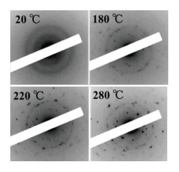
Fig. 6 ED patterns of the 75Li2S・25P2S5 glasses at various temperatures2) .
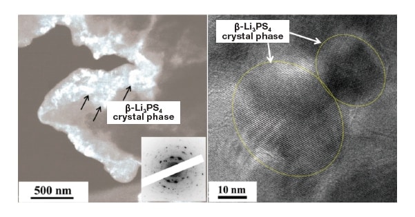
Fig. 7 DF image (left) and high-resolution TEM image (right) of the 75Li2S・25P2S5 glass-ceramics2) .
For the development of all-solid-state lithium-ion secondary batteries, it is necessary to suppress heat generation and ensure safety. Heat generation can be a main factor that deteriorates battery life and battery materials require thermal stability for operating environments. It is thus important to evaluate the exothermic behavior of the battery materials and clarify exothermic factors. In this study, we applied TEM observation techniques mentioned above to the positiveelectrode composites. The thermal stability of positive-electrode composites comprising LiNi1/3Mn1/3Co1/3O2 (NMC) and 75Li2S・25P2S5 (LPS) glass electrolytes was investigated. The all-solid-state cells using NMC–LPS composites exhibit good cycle performance7,8) . Figure 8 shows the differential scanning calorimetry (DSC) curve of the NMC–LPS positive-electrode composites after the initial charging. Two conspicuous exothermic peaks were detected in the temperature range from 300 °C to 400 °C, as indicated by arrows. To clarify the origin of these exothermic peaks, insitu TEM observations during heating were conducted for the NMC–LPS composites using a heating TEM holder. On the basis of TEM observation results and first-principles calculations, the main factors of the exothermic peaks and chemical reactions occurring between NMC and LPS were examined.
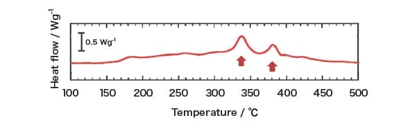
Fig. 8 The DSC curve for the NMC–LPS composites after the initial charge8) .
As a result of in-situ TEM observations, it was found that no structural change was detected in NMC, while crystallization occurred in LPS. Thus, we investigated the crystallization process in the LPS region with and without interfacial contact with NMC7) . Figure 9 shows a bright-field (BF) image of the LPS glass with interfacial contact with NMC and a series of ED patterns obtained from the region indicated by the circle in a BF image. In the initial state at 20 °C, a halo pattern indicating an amorphous state was observed in the ED pattern. When the temperature was increased above 20 °C, crystallization started at approximately 250 °C and then gradually proceeded up to 350 °C. However, above 400 °C, crystallization significantly progressed and diffraction spots and Debye–Scherrer rings exhibiting a high intensity appeared on the high angle side. Based on the analysis of ED patterns at each temperature, β-Li3PS4 crystalline phase precipitated in the temperature range of 200 °C–350 °C, while Li4P2S6 and Li2S crystalline phases were formed above 400 °C. Figure 10 shows a BF image of the LPS glass without interfacial contact with NMC and a series of ED patterns obtained from the region indicated by the circle in a BF image. Although crystallization occurred at approximately 250 °C and then gradually proceeded up to 500 °C, Debye–Scherrer rings exhibiting strong intensity, which were detected in Figure 9, were not observed. Based on the analysis of ED patterns, it was found that only β-Li3PS4 crystalline phase precipitated in the LPS region without interfacial contact with NMC. These in-situ TEM observation results demonstrated that the LPS crystallization process differed depending on the presence of an interfacial contact with NMC.

Fig. 9 The BF image indicating the morphology of the NMC–LPS composites after the initial charge and series of ED patterns obtained from the LPS glass area indicated by the blue circle in a BF image8) .
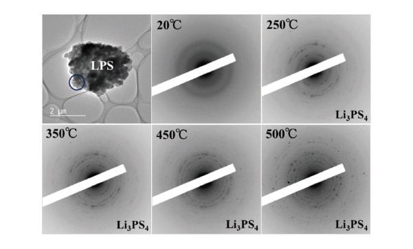
Fig. 10 The BF image indicating the morphology of the LPS glass without interfacial contact with NMC and series of ED patterns obtained from the area indicated by the blue circle in a BF image8) .
Figure 11 shows a series of DF images at each temperature, corresponding to the ED patterns in Figure 9. These images clearly show crystalline regions significantly increase from approximately 400 °C. That is, crystallization in the LPS glass that has interfacial contact with NMC significantly progressed at temperature above 400 °C, together with the appearance of Li4P2S6 and Li2S.
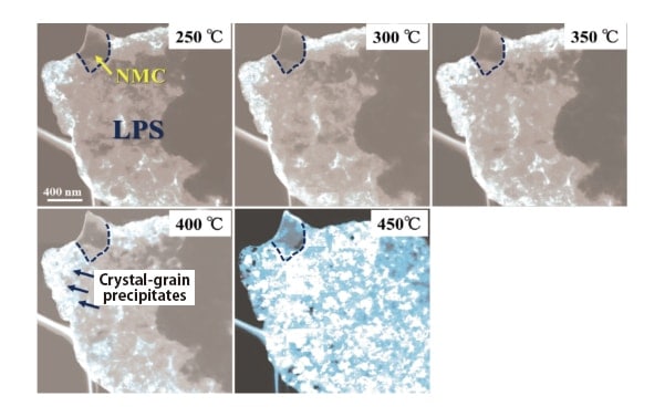
Fig. 11 A series of DF images obtained from the LPS glass region indicated by the blue circle in a BF image in Fig. 98) .
In-situ TEM observation indicated that the precipitation of Li4P2S6 and Li2S were involved in two of the exothermic reaction observed in the DSC curve. On the basis of the thermodynamic parameters of the chemical reaction process, the LPS crystallization behavior in the NMC–LPS composites was investigated. As a result, first-principles calculations suggested that two chemical reaction processes could occur as follows:
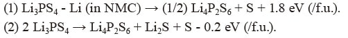
In the reaction process (1), Li is extracted from Li3PS4 by delithiated NMC and Li3PS4 is decomposed into Li4P2S6. When the exothermic reaction (1) occurs and Li4P2S6 crystallizes, its crystallization energy could appear as heat generation. In the reaction process (2), Li3PS4 is decomposed into Li4P2S6 and Li2S. When Li4P2S6 and Li2S crystallize, the crystallization energy of both Li4P2S6 and Li2S could appear as heat generation. Thus, the results of TEM observations and first-principles calculations together suggest that the exothermic reactions exhibited by NMC–LPS composites after initial charging are attributable to heat generation derived from the decomposition of Li3PS4 and the crystallization of Li4P2S6 and Li2S, as shown in Figure 12. These methods to evaluate thermal stability on the basis of in-situ TEM observation and first-principles calculation can be applied to other battery materials.
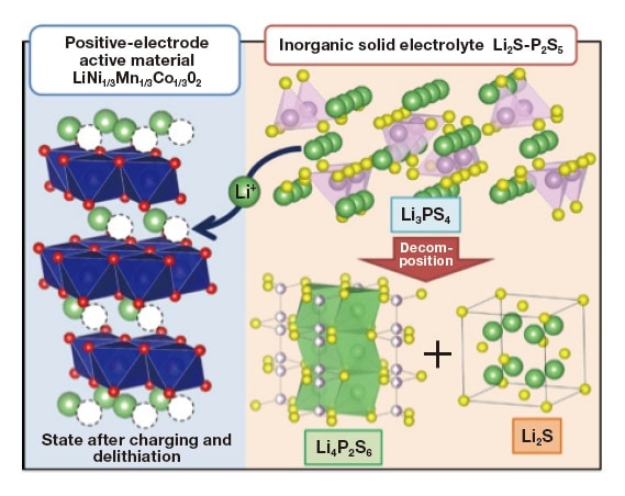
Fig. 12 Chemical reaction process occurring in the initially charged NMC–LPS composites during heating8) .
In the future work, we further calculate crystallization energy to precisely identify the factors of the exothermic reactions. Notably, the LPS crystallization behavior was found to differ depending on the presence of an interfacial contact between LPS and NMC. This could be attributed to the local bonding state of clusters and atoms in the amorphous state before crystallization. Therefore, as a next step, we will investigate the LPS crystallization behavior and the amorphous state in the sulfide glasses by a nano-beam electron diffraction method and differential pair distribution function analysis. For the development of all-solid-state lithium-ion secondary batteries, it is critical to evaluate thermal stability and exothermic factors of battery materials via various experimental technique.
Acknowledgments
This work is supported by Advanced Low Carbon Technology Research and Development Program of Specially Promoted Research for Innovative Next Generation Batteries (ALCA-SPRING) and in part by JSPS KAKENHI Grant Number 19H05814. First-principles calculations were performed at the National Institute for Materials Science (NIMS) by Dr. Takahisa Ohno. We also thank Prof. Masahiro Tatsumisago, Prof. Akitoshi Hayashi, and Prof. Atsushi Sakuda at Osaka Prefecture University for their help and discussion.
References
See more
