Keisuke Igarashi
In lithium-ion battery development, the goals of increasing energy density and output power, together with the importance of safety and reliability, have spurred intense research efforts to develop all-solid-state lithium-ion batteries, which use solid electrolytes and are expected to find applications in a variety of energy-storage systems. Of the various types of all-solid-state batteries under consideration, sulfide-based systems are considered particularly promising for their good formability properties and high ionic conductivity. However, sulfide-based solid electrolytes exhibit poor chemical stability in air, degrading by reacting with airborne water molecules to produce hydrogen sulfide. The storage capacity of lithium-ion batteries is also known to decrease with repeated iterations of the charge/discharge cycle, degrading battery performance. Analyzing the mechanisms of these degradation processes is crucial for high-performance battery development.1-6)
Experimental analyses of all-solid-state-battery samples via transmission electron microscopy (TEM) must be performed without exposing samples to the ambient environment to prevent material degradation due to atmospheric moisture. In this article we describe an environmental-isolation system for transporting measurement samples between laboratory instruments without exposure to the ambient environment; this approach allows all stages of the experimental process, from preprocessing to observation, to be performed without ever bringing samples into contact with air. We use this system to conduct transmission electron microscopy (TEM) analyses of structural changes in sulfide-based all-solid-state batteries induced by charge/discharge cycling. In addition, we have developed a technique for in-situ observations under gas injection, which we use to perform real-time observations of the degradation process of sulfide-based all-solid-state batteries in air.
For these experiments we used an HF5000 TEM/STEM system featuring a cold-field-emission electron gun and a probe-forming aberration corrector.7) Our TEM sample holder is an environmentally-isolated holder designed to allow both TEM observation and FIB (focused ion beam) processing. Figure 1 is a conceptual diagram illustrating our environmentally-isolated system for linking FIB and TEM procedures. The grip region of the sample holder is equipped with an open/close dial that adjusts the position of the sliding side wall of the sample holder, allowing samples to be separated from the surrounding environment. This environmental-isolation system allows all steps in our experimental procedure, from sample preprocessing to observation and analysis, to be performed without exposing samples to the ambient environment. Samples before and after charge/discharge cycling were processed via FIB-SEM to prepare thin film sections spanning the electrode/solid-electrolyte interfaces; these sections were then transferred to the HF5000 without exposure to the ambient environment. We performed TEM/STEM observations to visualize structural changes before and after charge/discharge cycling, as well as EDX/EELS analyses to characterize element distributions and chemical states.
To observe the process of material degradation in air, we use a differential-evacuation system featuring the ability to inject gas directly onto a sample mounted in the HF5000.8-9) This system injects gaseous air onto thin-film TEM samples through a gas-injection nozzle located inside the mirror unit, thus allowing degradation analysis via in-situ observation of the reactions of sulfide-based all-solid-state batteries in air.
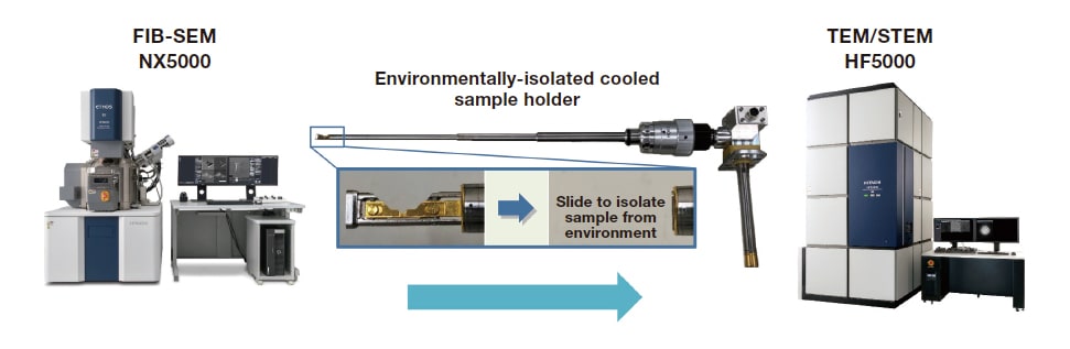
Fig. 1 Conceptual diagram of environmental-isolation system linking FIB and TEM procedures.
Our observation samples were all-solid-state batteries featuring the sulfide-based solid electrolyte Li6PS5Cl. These were fabricated via powder compression with LiCoO2 as positive-electrode material and graphite as negative-electrode material. Figure 2 shows charge/discharge curves for one such sulfide-based all-solid-state battery. Before charge/discharge cycling, the capacity of this battery was 412 μAh; over the course of 13 charge/discharge cycles, its capacity fell from 357 μAh to 291 μAh, a decrease of approximately 20%. We performed TEM observations of this sample to investigate structural changes induced by charge/discharge cycling.
Figure 3 shows simultaneously-acquired STEM/SEM images of the positive-electrode/solid-electrolyte interface before and after charge/discharge cycling. Comparing STEM/SEM images acquired before and after charge/discharge cycling allows observation of structural changes—in the positive electrode and in the solid electrolyte—induced by the charge/discharge process. Looking at the solid electrolyte in the vicinity of the interface, we see that charge/discharge cycling has the effect of increasing the grain size of the electrolyte material, decreasing the electrolyte surface area and thus reducing the battery capacity.
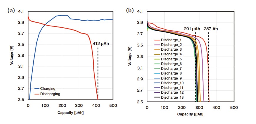
Fig. 2 Charge/discharge curves for sulfide-based all-solid-state lithium-ion battery studied in our experiments.
(a) Before charge/discharge cycling. (b) After charge/discharge cycling.
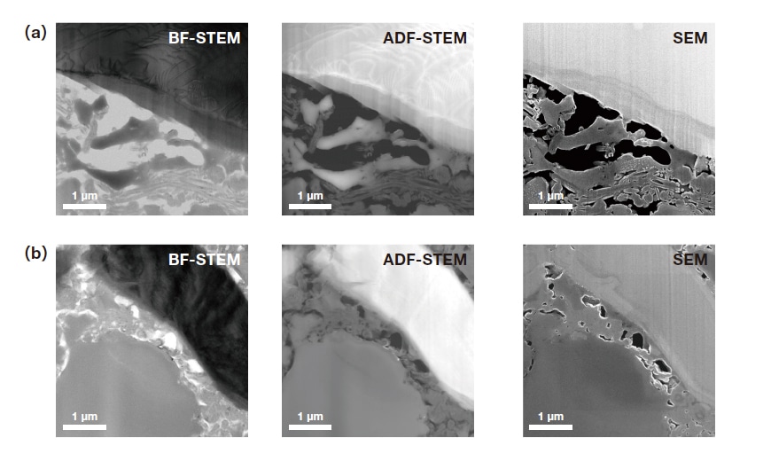
Fig. 3 STEM/SEM images of positive-electrode/solid-electrolyte interface.
(a) Before charge/discharge cycling. (b) After charge/discharge cycling.
Figure 4 shows STEM-EDX elemental-mapping images of the negative-electrode/solid-electrolyte interface before and after charge/discharge cycling. We found that charge/discharge cycling modifies the distributions of the elements P, S, and Cl, and we performed EDX elemental-mapping analysis to investigate the changes in element distributions accompanying the reduction in battery capacity induced by charge/discharge cycling. Before charge/discharge cycling, we observe many regions with non-uniform distributions of P, Cl, and other elements. After charge/discharge cycling, most of these regions have decreased in size, yielding element distributions of greater uniformity. This indicates that, during charge/discharge cycling, P and Cl migrate within the solid electrolyte to make their distributions more uniform, a process that contributes to changes in battery capacity.
We also performed STEM-EELS analysis before and after charge/discharge cycling. EELS is capable of detecting Li, a n element which cannot be detected via EDX, and is thus a useful tool for qualitative characterization of the distributions and states of Li ions. Figure 5 shows STEM/EELS spectra for the negative-electrode/solid-electrolyte interface before and after charge/discharge cycling. Within the solid electrolyte near the negative-electrode interface, the Li K-shell absorption edge is detected before charge/discharge cycling, but disappears after charge/discharge cycling. From this finding we infer that, within the solid electrolyte near the electrode interface, Li intercalation is obstructed during charge/discharge cycling.
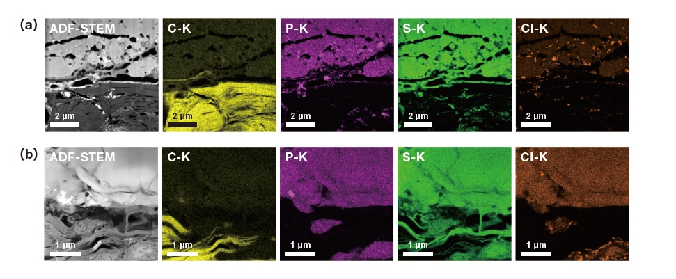
Fig. 4 STEM-EDX elemental-mapping images (a) before and (b) after charge/discharge cycling.
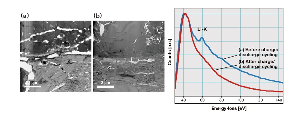
Fig. 5 STEM-EELS spectra (a) before and (b) after charge/discharge cycling.
Our observation samples for this analysis were all-solid-state batteries featuring the sulfide-based solid electrolyte Li3PS4, with LiCoO2 as the positive-electrode material and In as the negative-electrode material. These were processed via FIB to prepare thin-film sections spanning the positive-electrode/solid-electrolyte interface. Figure 6 shows results of in-situ observations characterizing the degradation process for a thin-film sample before and after injection of gaseous air. We use TEM/STEM images to visualize morphology changes and electron-diffraction patterns to assess crystallinity. For the sample in vacuum (before air injection), the electron-diffraction pattern exhibits Debye-Scherrer rings, indicating a polycrystalline sample [Figure 6(a)]. By comparison, Figure 6(b) shows the electron-diffraction pattern captured 1 hour after injecting air (10 Pa); compared to Figure 6(a), we see fewer diffraction spots, indicating decreased crystallinity. The electron-diffraction pattern captured 3 hours after injecting air [Figure 6(c)] exhibits halo rings, indicating an amorphous material from which the crystalline structure has disappeared. In the ADF-STEM images in Figure 6(a,b), we see multiple crystal lattices, presumably due to Li3PS4, and a large number of microcrystals. In Figure 6(c), by contrast, no crystal lattice is observed, indicating that the material has become amorphous in agreement with the results of electron-diffraction analysis. The TEM images indicate significant distortion in the shape of the interface, accompanied by extensive morphological changes. These effects result from structural changes induced by chemical reactions between the Li3PS4 solid electrolyte and the injected air.
Figure 7 shows STEM-EDX maps of the Li3PS4 solid-electrolyte region (a) before and (b) after gas injection. Looking at the oxygen map, we see that oxygen is not present in the solid electrolyte before gas injection, but is present throughout the solid electrolyte after gas injection. This indicates that the solid electrolyte reacts with air to form oxides. We see also that the sulfur concentration decreases; this is due to the loss of sulfur from the Li3PS4 solid electrolyte in the form of gaseous hydrogen sulfide. Finally, Figure 8 shows the results of STEM-EELS analysis to characterize changes in the chemical state of Li before and after gas injection. Spectral analysis of the Li3PS4 solid-electrolyte region reveals that the Li-K peak in the EELS spectrum shifts in position and changes shape after gas injection; this is due to the conversion of the solid electrolyte from sulfide to oxide, yielding a shift in the chemical state of Li that is captured by the EELS analysis.
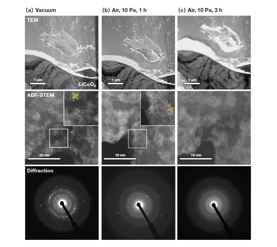
Fig. 6 TEM/STEM images and electron-diffraction patterns before and after gas injection.
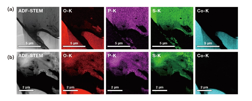
Fig. 7 EDX maps before and after gas injection.
(a) Before gas injection (vacuum). (b) 3 hours after gas injection (air, 10 Pa).
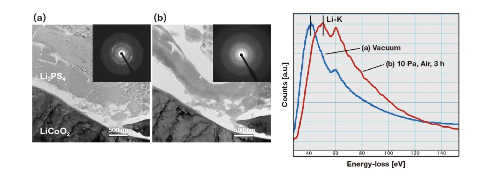
Fig. 8 Results of STEM-EELS analysis before and after gas injection.
(a) Before gas injection (vacuum). (b) 3 hours after gas injection (air, 10 Pa).
In this work we presented a TEM analysis solution for all-solid-state lithium-ion batteries involving an environmental isolation system and a technique for in-situ observations under gas injection. This analysis allowed us to observe transformations induced by charge/discharge cycling, including structural changes in solid electrolytes and changes in the distributions of elements within samples. We also performed in-situ observations of the degradation processes in air, visualizing the transition from crystalline to amorphous structure in the solid electrolyte and a corresponding shift in the chemical state of Li. Techniques for environmentally-isolated observation are essential components of analysis and characterization solutions for the increasingly high-performance materials of modern batteries—and promise to play a key role in the development of high-performance all-solid-state lithium-ion batteries.
References
About the authors
Keisuke Igarashi
CT Solutions Development Unit, CT System Products Division, Core Technology and Solutions Business Group, Hitachi High-Tech Corporation
