Jiro Usukura*1, Akihiro Narita*1, Tomoharu Matsumoto*1, Eiji Usukura*1, Takeshi Sunaoshi*2, Yusuke Tamba*2, Yasuhira Nagakubo*2, Junzo Azuma*2, Takashi Mizuo*2, Kazutaka Nimura*2, Masako Osumi*3, Ryuichiro Tamochi*2, Yoichi Ose*2
Cryo-electron microscopy (cryo-EM), which has become gradually popular in recent years, is used exclusively herein for single-particle analysis of purified proteins and viruses in their native state. Single-particle analysis (a kind of image processing) has thus far been applied to purified molecules stained negatively. However, negative staining is basically air-drying, even if the staining solution encompasses a molecule and its surroundings quickly, and thus it is difficult to entirely prevent structural changes. Moreover, the images obtained vary depending on the penetration of the staining solution. In cryo-EM, however, purified protein molecules are quickly frozen and observed without any further treatment, which allows even biological samples to be observed at practical EM resolution. This is a crucial point, because conventional EM preparation techniques such as freeze-etching replicas or ultra-thin sections incur a reduction of resolution during pre-treatment. However, raw protein samples are extremely vulnerable to irradiation damage by electron beams; where even for observations at liquid-nitrogen temperature, the samples are reportedly damaged at a beam irradiation of approximately 20 electrons/Å2. This implies that raw protein samples must be observed under an illumination of 1–3 electrons/Å2. Though challenging, this feat is made possible by the recent development of high-sensitivity cameras based on direct detection of electrons (DD cameras). Further, single-particle analysis does not require the crystallization of protein molecules, but allows structural analysis in dispersed systems. The highest spatial resolution recently obtained from single-particle analysis is 3Å (Meyerson et al., 2016), which is approaching the resolution of X-ray crystallography. Moreover, it should be noted that these analytical results were obtained for samples in a frozen state close to their native state. Meanwhile, cryo-EM is not only useful for single-particle analysis, but is also an extremely powerful tool for conventional structural observations. Indeed, cryo-EM observations of frozen sections have successfully revealed the molecular structure of functioning organelles, ribosomes, and the desmosomes that mediate adhesion between cells (Al-Amoudi et.al., 2004). In the future, cryo-EM will become an essential tool for pathology of cells. Recently, cryo-EM has been used for structural analysis of the infection process of the influenza virus in cells (Fontana & Steven, 2015). In general, for understanding life phenomena, it is very important to know the structure of proteins, their complexes in a functioning state and their spatial structure, and how such proteins are disposed within a cell. Cryo-EM is clearly an essential tool for this purpose. Unfortunately, however, cryo-EM is not sufficiently widespread in Japan compared to Europe and the United States. Instead, cryo-EM observations of fresh tissue and cells depend on preprocessing equipment such as quick freezers, cryo-microtomes and other significant investments—on the order of 700 million yen in total—which is likely the primary factor preventing the more widespread use of cryo-EM. However, if these instruments are required for future progress in the life sciences, there is no choice but to equip laboratories with them. Cryo-instrumentation is now rapidly being facilitated in leading European and American universities, and the development of cryo-systems including preprocessing instruments has occurred almost entirely in the EU, while Japanese contributions are disappointingly few and far between. Although we are something of a latecomer to the marketplace, we have now developed a new cryo-EM that detects both transmission and surface images simultaneously in the frozen state. Herein we report the features and applications of this new instrument.
We aim to develop a cryo-EM that everybody can use easily in a wide range of scientific fields with an economical budget. In particular, a low-voltage cryo-EM (scanning transmission electron microscope, or STEM) was developed based on a scanning electron microscope (SEM: SU 9000) equipped with a STEM detector to capture SEM and STEM images simultaneously. Additionally, the sample preparation method is also important and should be developed together with the EM. Indeed, if the samples are not processed in an appropriate way, the EM will fail to realize its full capability, even if designed to the most exacting performance standards, and the reliability of the observed results will be impaired as well. Thus, the development of a cryo-EM and the development of the sample preparation appear inseparable. Therefore, we developed a device for cell-membrane removal (i.e., unroofing) to facilitate observations of the membrane cytoskeleton.
Because our research project was supported by government funds, we should develop the most powerful cryo-EM in the world. However, a 300 kV cryo-EM has already been offered on a commercial basis that is, to some degree, user-friendly and also has produced world-record data. Although this instrument is extremely expensive as its disadvantage, the development of a great deal of elemental technology would be necessary to exceed this microscope, which is not feasible to achieve with the funding we currently receive from the Japan Agency for Medical Research and Development (AMED). This is the primary reason we chose not to target atomic resolution in cryo-EM development. Nonetheless, the low-accelerating-voltage (i.e., only 30 kV) cryo-EM developed in this study is capable of simultaneous STEM and SEM measurements, which offers several prominent advantages and may come to occupy a highly competitive position within EM technologies. For example, because images of frozen biological samples in conventional cryo-EM typically exhibit extremely low contrast at the focal point, images are usually made by shifting the focus to the underside of the sample to yield a phase contrast (i.e., Fresnel contrast), which results in a decrease of the original resolution of the EM. To perform single-particle analysis of the images obtained in this way, both a correction of the contrast transfer function (CTF) and the collection of a large number of images are needed. However, the new cryo-EM developed in this project allows transmission images to be formed in the STEM optical system. In STEM, images are obtained by scanning an extremely focused electron beam over the sample, and therefore images are a bitmap of electrons transmitted through the sample. Thus, the image obtained is not formed by an objective lens and does not suffer as much from the CTF. As a matter of course, images were observed at the focal point without any reduction of the resolution. Thus, the new cryo-EM developed herein is especially useful for single-particle analysis, where it yields good results with a relatively small number of images compared to conventional cryo-EM in transmission electron microscopy (TEM) mode. Another major difference between the new STEM cryo-EM and conventional TEM is the method of image detection. Whereas TEM requires a camera to capture the image, STEM requires only a scintillator to capture electrons. This distinction may become meaningful and increasingly important in the forthcoming development of EM. Today, the complementary metal-organic-semiconductor (CMOS)-based DD cameras installed in cryo-TEMs offer a much better performance, but these cameras are very expensive (nearly 100 million yen per unit). The scintillators installed in STEM, however, capture electrons passing through the sample (i.e., position sensitive), and thus the sensitivity should be sufficient to count electrons. For example, if it proves possible, applying a thick coating of good fluorescent material may achieve the high sensitivity required for single-electron detection, whereupon images of quality comparable to that of DD cameras could be obtained at vastly lower cost. The feasibility of such a detector depends on future study.
Because the total size of the cryo-EM developed in this project is compact, and indeed is the same as the Hitachi SEM (SU 9000) used as a development base machine, it was not necessary to create a special electron microscopy room but to simply install it in the corner of the laboratory. We estimate that many researchers in the life sciences would be satisfied with this cryo-EM, because with it single-particle analysis is easily feasible with a small number of images even at 1 nm resolution, and the fine structure in the cell can be observed in the native state at the same resolution. We thus aimed to develop a cryo-EM with the above advantages.
Of all the elemental technologies encompassed by our development plan, the most crucial component was the development of a cryo-transfer holder. Approximately 2/3 of the holder arm was formed by a double-walled vacuum pipe that was almost entirely filled with liquid nitrogen, which increased the cooling rate of the specimen holder. We also added a vacuum system to release the gas from the liquid nitrogen in the pipe, and we tested the effect of converting the liquid nitrogen into slush nitrogen in what was the world's first attempt to use slush nitrogen in a cryo-transfer holder. In this way, we succeeded ultimately in reaching temperatures as low as −190°C. Moreover, we optimized the incoming and outgoing flow paths for liquid nitrogen to improve the speed and efficiency of cooling. Practical observation of samples was carried out while maintaining the specimen holder at −180°C. In the present state of the cryo-EM, it was difficult to observe specimens for extended periods at temperatures lower than −185°C because the images drifted with the temperature fluctuations. This drift is owing to an influx of heat into the cryo-transfer holder from the contact region between the holder and the stage, which is positioned at the tip of the holder. Based on this observation, we expect that the development of a non-contact stage may reduce image drift to allow long-duration observations.
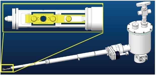
Fig. 1 CAD diagram of the prototype cryo-transfer holder. The inset (upper left) shows an enlarged view of the sample holder at the tip.
Because the sample in a cryo-EM is held at an extremely low temperature, a contamination trap cooled to a temperature below that of the sample is needed to prevent contamination of the samples. In our system, the arm portion of the trap was also comprised of a pipe in which liquid nitrogen may be introduced at a point near its tip. We also added a gas-exhaust system and succeeded in cooling the trap to −200°C by converting the liquid nitrogen into a slush. The shape of the tip of the trap was designed to surround the sample region at the tip of the cryo-transfer holder. In addition, by cooling the buffer tank of the microscope, we achieved a vacuum strength in the sample chamber of 2 × 10⁻⁶ Pa, to be compared to the conventional strength of 7 × 10⁻⁶ Pa. These improvements succeeded in almost entirely preventing the reformation of ice crystals on the sample.
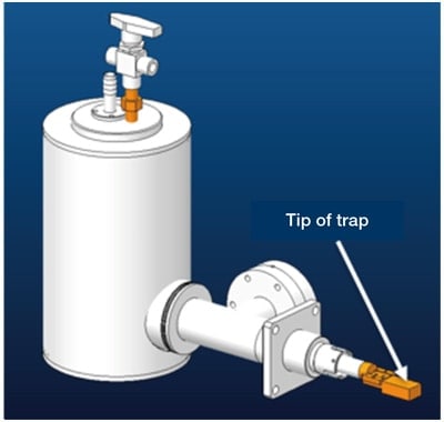
Fig. 2 CAD diagram of anti-contamination trap. The use of slush nitrogen succeeded in cooling to −200°C. The shape of the tip of the trap was designed to surround the tip of the sample holder (the sample region).
As mentioned previously, even high-performance observation instruments cannot achieve their full performance if the sample is processed incorrectly, and in such cases one cannot expect to obtain reliable measurement results: The development of the instrument itself and of techniques for preparing samples truly are two sides of the same coin. Unfortunately, preprocessing techniques for cryo-EM observations is another area in which Japan lags behind Europe and USA. The commonly-used “orthodox” methods for cryo-EM observation; i.e., the cryo-section of rapidly frozen samples; was developed in Europe. This process involves a collection of preprocessing instruments with a total cost on the order of 100 million yen. We have therefore adopted the unroofing method for observation of the membrane cytoskeleton instead of using the orthodox frozen-section method, where unroofing means mechanical removal of the cell membrane. In this case, the membrane cytoskeleton attached on the ventral cell membrane became observable in cryo-EM after removal of the dorsal cell membrane. We have improved and redeveloped the technique of ultrasonic unroofing conventionally used as a preprocessing step for freeze-etching replica methods. In this approach, soluble components in the cell are washed away so as to increase the contrast of the cytoskeleton and other organelles. Samples processed in this way exhibited a number of unexpected advantages, including panoramic observations of the cytoplasmic surface of the cell membrane. However, the commercially available probe-type ultrasonic generator used without modification produced an output power that was too strong to properly regulate the unroofing, and its excessive output power led to certain problems with reproducibility. For example, when applied to cells cultured on a carbon support film on EM grids, the cells were completely destroyed and removed. An appropriate output power for unroofing was found to be approximately 1 W or less. In contrast, the output power of commercially available probe-type ultrasonic generators is typically 50 W or more, and it is difficult to control it to under 5 W. Therefore, we customized an ultrasonic generator with an output power of 5 W or less, with an option to precisely regulate the power below 1 W. Our cell-membrane removal (unroofing) apparatus thus consisted of (1) this custom-made low-output-power ultrasonic generator, together with (2) a position controller to bring the ultrasonic probe near the sample accurately, and (3) a stereo optical microscope to observe the process of cell-membrane removal (Figure 3). With this apparatus, the removal of the cell membrane became extremely simple and easy. We also found this tool to be useful in preparing samples not only for cryo-EM but also for other types of observation instruments. In particular, although it was difficult to observe the intracellular fine structure with atomic force microscopy (AFM), unroofing enabled us to view the supra molecular structure inside of the cell for the first time in water (Usukura et al., 2016). Figure 5 shows an AFM image of the intra-cellular fine structure prepared using the apparatus we developed, wherein molecular structure analysis of the individual actin filaments in the cell is also possible.
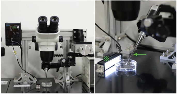
Fig. 3 The prototype cell-membrane removal (i.e., unroofing) apparatus constructed herein, as viewed from the front (left) and at short distance from an angle (right). The apparatus consists of a low-output-power probe-type ultrasonic generator (indicated by an arrow) a position controller for this probe, a stereo microscope, and a horizontal illuminator (indicated by an asterisk).
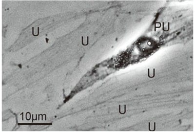
Fig. 4 Phase-contrast optical microscopic image of cells after unroofing. Membrane cytoskeletons (stress fibers) are visible above the center of cell membranes (indicated by “U” symbols). The region marked “PU” indicates cells from which the cell membrane was partially removed.
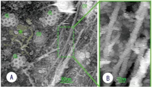
Fig. 5 (A) AFM image showing the structure of the membrane undercoat of NRK culture cells. (B) Enlargement of the boxed area of A. The short periodicity of the actin filaments is clearly observed. “CL” indicates clathrin coat. “CV” indicates caveola. Asterisks indicate smooth-surfaced endoplasmic reticulum. (Sci. Rep., 6: 27472, 2016)
The simultaneous cryo-STEM and cryo-SEM observation of membrane cytoskeletons in their native state, which was an original goal of this development project, has been achieved. Indeed, such observation has become almost routine (Figure 6). Because soluble components in a cell are washed away upon unroofing, the cytoskeleton could be observed with sufficient contrast on focus. Surprisingly, ribosomes and endoplasm reticulum remained partially intact after unroofing, and were observed well together with the membrane cytoskeleton (Figure 7). In particular, many organelles such as mitochondria, smooth endoplasmic reticulum (ER), rough ER and ribosomes were detected with extremely high contrast, despite the presence of partially unroofed cells in which many soluble components still remained. A fortunate and unexpected finding was that regions of thickness estimated at 200 nm or more could be clearly observed. We are unsure whether or not this is a feature of the STEM optical system, but it became evident that the STEM is capable of describing intracellular fine structures even at 30 kV accelerating voltage. This represents a crucial first step toward the development of new types of EMs in the future.
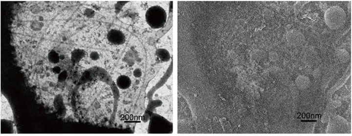
Fig. 6 Simultaneously recorded cryo-STEM (left) and cryo-SEM (right) images (for an unfixed sample). Initially, the sample is fully embedded in ice and the SEM image is flat owing to the ice coating. As the electron-beam irradiation induces a temperature increase, a portion of the ice sublimates, yielding the structure seen in the figure at right.
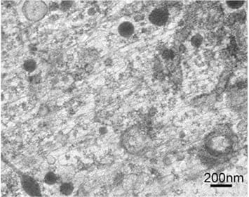
Fig. 7 Cryo-EM images of unroofed cell without chemical fixation. The cytoskeleton consisting of actin filaments and microtubules is observed well together with smooth endoplasmic reticulum (ER), rough ER and ribosomes in spite of the presence of unroofed cells.
Another important finding was derived from the application research carried out under this development project. As discussed above, the objective lens is not directly involved in image formation in STEM optics, which is optimal for single-particle analysis. This advantage is particularly prominent in our developed low-voltage cryo-EM installed with a cold-field emission electron gun, which generates a very focused electron beam (0.34 nm in diameter). Indeed, the single-particle analysis of the actin filaments and molecular structure calculated from only 20 images obtained by our 30 kV STEM exhibited a much higher resolution than that obtained by conventional 100 kV TEM (Figure 8). In single-particle analysis using an adenovirus stained in the conventional way, 18 images were sufficient to obtain the molecular structure of the virus at 5 nm resolution (Figure 9). Because the images were obtained without CTF correction and with high contrast on focus, the molecular structure was determined more precisely than in the conventional way by single-particle analysis using a small number of images. This fact suggests the possibility of in situ single-particle analysis revealing the real molecular structure in a cell, but not purified molecules.
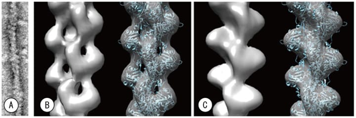
Fig. 8 Comparison of cryo-EM developed here vs. standard TEM. From negative-stained images (A) we performed three-dimensional reconstruction via single-particle analysis, taking into account the helical symmetry. (B) 30 kV STEM image captured with new cryo-EM described herein, and (C) 100 kV image captured with a standard TEM. Upon fitting to an atomic coordinate model (Oda et al., 2009), the three-dimensional image reconstructed from the 100 kV standard TEM image exhibited some regions of disagreement, while the three-dimensional image reconstructed from the STEM images obtained with our new system exhibit excellent agreement.
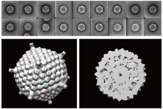
Fig. 9 Eighteen images of adenovirus particles captured with new cryo-EM developed in this paper (upper) and reconstruction based on these images (lower).
Although the new 30 kV cryo-EM with cryo-transfer holder developed herein was primarily to observe frozen samples of living cells, cryo-EM seems to be a useful tool for materials science because of its remarkable reduction of irradiation damage to the samples. In fact, a cryo-holder, though not a cryo-transfer holder, has been used in materials science to reduce irradiation damage, wherein the cooling of the cryo-holder is initiated after being placed into the microscope. This delayed cooling of the cryo-holder is not a problem in the case of metallic samples; but in materials that include water, ice crystals are formed upon cooling and break the fine structure. Consequently, cryo-holders are not useful for materials including water. Instead, biological samples and materials including water must be quickly frozen to produce amorphous (non-crystalline) ice, and then the frozen sample must be transferred into the cryo-EM while maintaining its frozen state using the cryo-transfer holder. The formation of crystalline ice is a crucial problem in EM study on liquid substances. We have recently succeeded in observing nano-bubbles (gas bubbles approximately 50–100 nm in size) formed in water (Figure 10). These could possibly be observed with conventional cryo-TEM systems as well, but the ability of our system to capture simultaneous STEM and SEM images offers proof that these bubbles actually do exist in the water. This is a useful new application of the cryo-EM that we have developed. Strong future demand of this cryo-EM is anticipated in areas such as cosmetics, pharmaceuticals, foodstuffs and soft materials, and the research institute of soft material sections is anticipated in future.
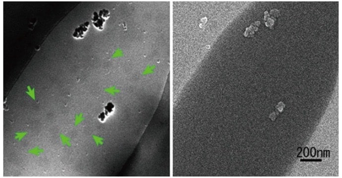
Fig. 10 Nanobubbles formed in water, as imaged using the new system developed herein. These observations were made by pouring water into holes in a QUANTIFOIL membrane and rapidly freezing; the STEM (left) and SEM (right) images were obtained simultaneously. Bubbles are indicated by arrows. The bubbles frequently appear dark in the STEM image.
We used an SEM (SU 9000, Hitachi High-Tech) installed with a STEM detector as a base for the development of a new cryo-EM. However, it would be desirable to design an instrument based on a STEM core with added capabilities for high-performance SEM. To retain the image quality of conventional EM in the cryo-EM, we hope to increase the scan speed to prevent drifting associated with cooling. A decade ago, high-resolution AFM imaging required 20 min per frame, but today speeds of 10 s per frame are becoming increasingly standard. In contrast, SEM scan speeds have remained unchanged (1 min per frame) for some 30 years. A method of increasing scan speed in SEM is to increase the probe current, but this increases the risk of sample damage. We hope to design new cryo-EM systems capable of producing high-magnification, high-quality images by combining the newest drift-correction techniques with increased sensitivity of the detector system.
This work was supported by the Medical Research and Development Programs Focused on Technology Transfer (Development of Advanced Measurement and Analysis Systems) of the Japan Agency for Medical Research and Development (AMED).
References
See more
