
Akira Sawaguchi
MD & PhD
Professor
Ultrastructural Cell Biology, Department of Anatomy,
Faculty of Medicine, University of Miyazaki
Director
Bio-Imaging Lab,
Frontier Science Research Center, University of Miyazaki
The heart, kidneys, liver, and other organs that keep us alive have an intricate three-dimensional structure made of cells and connective tissues that confer their physiological function. Breakdown of these cells and tissues leads to a loss of function and normal condition, finally turning into abnormal pathology and resulting in the development of disease. Light microscopes are the main tools used for histopathological diagnosis, which seeks to unlock the etiology of such diseases in the form of morphological changes, but electron microscopy is needed to investigate morphological changes in fine detail. Nevertheless, the latter technique is complicated by the difficult and time-consuming procedures needed for sample preparation and the need for electronic staining, which requires strictly-regulated uranium compounds. A pressing goal for R&D efforts into regenerated organs is the recreation of their three-dimensional structure. Achieving this goal will require convenient and rapid sample preparation techniques for capturing the fine-grained structure of cultured cells and the three-dimensional structure of the insides of organs in intricate detail, and also microscopic techniques useful for screening the quality of regenerated organs.
To solve these problems, we have been working on a new electronic staining procedure that does not use uranium compounds, which has been a long-standing challenge, and successfully established a protocol for conveniently and rapidly imaging the fine-grained morphology of the cells and tissues that make up organs in intricate detail at electron-microscopy resolution. This article discusses the new direction in which tabletop low-vacuum scanning electron microscopes are headed, allowing wide-ranging biomedical and clinical applications such as the histopathological diagnosis of tissue and evaluation of the morphological quality of regenerated organs.
The TM4000PlusII tabletop scanning electron microscope is, as its name suggests, a compact instrument that fits on a standard desk. It features a holder for light microscope slides with paraffin sections(Figure 1). Slides can be easily placed on and removed from the holder and, provided paraffin sections 5 to 30 μm in thickness are used, no troublesome height adjustment is required. By saving image files with information about the position where the images were obtained, the holder can return to the same position each time a slide is reinserted.
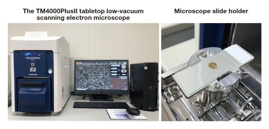
Fig. 1 TM4000PlusII tabletop scanning electron microscope(left). Slide holder(right). Slides can be easily placed and removed, and no height adjustment is required.
The TM4000PlusII operates at a low vacuum of 30 to 50 Pa, so that negative charge accumulated on the nonconductive paraffin section and slide as a result of electron irradiation is neutralized by positively charged ions generated in the remaining gas. This reduces the electrostatic charge that hinders observation(Figure 2).
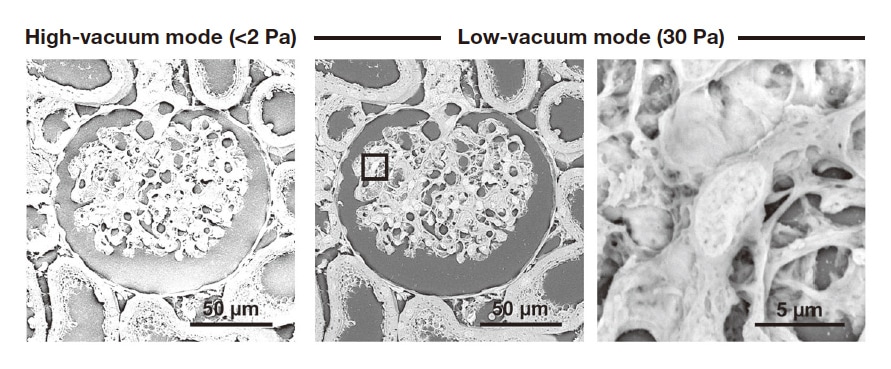
Fig. 2 Micrographs illustrating the difference between high- and low-vacuum modes. Rat renal corpuscle. High-vacuum mode(<2 Pa) (left). High electrostatic charge prevents analysis. Low-vacuum mode(30 Pa) (center and right). With the electrostatic charge greatly reduced, the area within the square in the center micrograph can be analyzed at high magnification(right).
The electronic staining technique now widely used was first developed by Watson in 1958, and is based on uranyl acetate and lead1,2). However, uranium compounds are strictly regulated, and all steps of the process—from purchase to storage, use, and disposal—are quite complicated. Electron microscopists have long desired a new electronic staining technique that does not require uranium compounds. In the potassium permanganate/lead staining protocol that we developed3), paraffin sections for light microscopy are treated with an aqueous solution of 0.2 % potassium permanganate for 5 minutes, washed with water, treated with Reynolds’ lead citrate solution for 3 minutes, and then washed with water and dried. The resulting specimens are ready for observation(Figure 3). Our protocol allows convenient and rapid sample preparation, and differs from the conventional technique only in that 0.2 % potassium permanganate is used instead of 2 % uranyl acetate. The time required for electronic staining remains the same, at about 10 minutes.
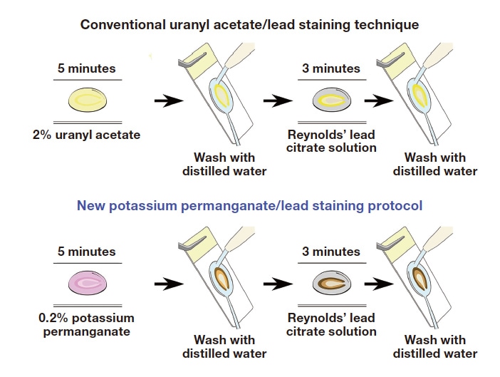
Fig. 3 Conventional uranyl acetate/lead staining technique(top) and new potassium permanganate/lead staining protocol(bottom)
The new potassium permanganate/lead staining method provides high-contrast staining comparable to that for the conventional uranyl acetate/lead staining technique. The attractiveness of the ability to convert samples prepared for light microscopy into samples for electron microscopy, and the power of low-vacuum scanning electron microscopy, are obvious. Elemental analysis showed that lead deposition enhanced by potassium permanganate oxidation resulted in a backscattered electron intensity sufficient to make the fine-grained structures of cells and tissues visible3).
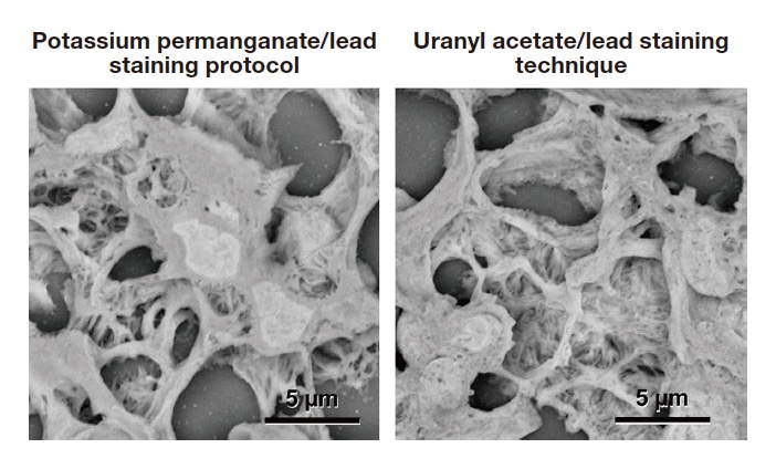
Fig. 4 Rat renal glomerulus. This side-by-side comparison shows tissue stained with the new potassium permanganate/lead staining protocol(left) and conventional uranyl acetate/lead staining technique(right). This comparison highlights the attractiveness of the ability to convert samples prepared for light microscopy into samples for electron microscopy and the power of lowvacuum scanning electron microscopy. Fixing fluid: 2 % paraformaldehyde + 2.5 % glutaraldehyde. Section thickness: 5 μm.
Paraffin sections are generally observed in backscattered-electron mode. Since the resulting micrographs differ depending on the accelerating voltage, the voltage must be adjusted to suit the objective of the microscopy observations. Figure 5 shows micrographs obtained at four different accelerating voltages ranging from 5 to 20 kV. Note that low-contrast but clear images of the cell surface can be obtained at low accelerating voltages, whereas high-contrast but unclear images are obtained at high accelerating voltages. Based on our experience, we recommend a voltage of 15 to 20 kV for low-magnification(<500×) microscopy for clearly imaging the overall tissue, and a voltage of 5 to 10 kV for high-magnification(≥500×) microscopy for imaging the intricate architecture of cell surfaces.
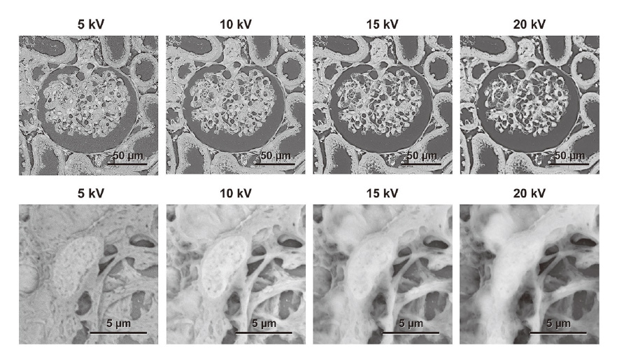
Fig. 5 Micrographs obtained at different accelerating voltages. Note how a low accelerating voltage reduces the contrast but makes the cell surface architecture clear, while a high accelerating voltage increases the contrast but obscures the architecture. We recommend using a voltage of 15 to 20 kV for low-magnification(<500×) microscopy and 5 to 10 kV for high-magnification(≥500×) microscopy.
Paraffin sections for light microscopy are typically cut to a thickness of only around 5 μm so as to be permeable to light. Cell nuclei do not overlap at this thickness. However, we previously reported the use of low-vacuum scanning electron microscopy with thick paraffin sections(15 to 30 μm)2), based on the detection of backscattered electrons. The greater sample thickness allows the three-dimensional structure of tissue cells to be imaged. Figure 6 shows images obtained from thick sections of the rat renal glomerulus, renal tubules, and the ciliated epithelium of the bronchiole stained using the potassium permanganate/lead staining protocol. Although these micrographs were obtained using a tabletop scanning electron microscope, they successfully capture fine cilia and other three-dimensional details not readily imaged with light microscopy.
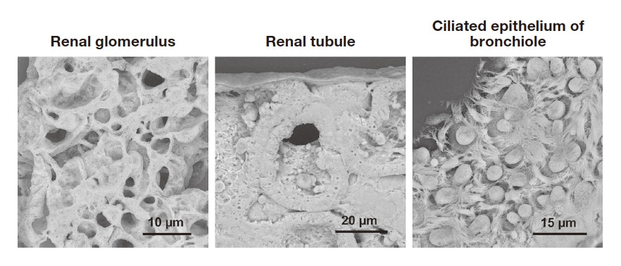
Fig. 6 Thick paraffin section micrographs of rat organs. Cutting sections to 20 μm rather than the standard 5-μm thickness gives the specimens depth, allowing clear imaging of the three-dimensional structure of tissue cells. Fixing fluid: 2 % paraformaldehyde + 2.5 % glutaraldehyde. Section thickness: 20 μm.
All of the electron microscopy samples described so far were fixed using a standard half-strength Karnovsky's fixing fluid(2 % paraformaldehyde + 2.5 % glutaraldehyde). Standard histopathology specimens, however, are normally fixed using a 10 % formalin solution(4 % paraformaldehyde alone). Figure 7 show a scanning electron microscopy image of rat bronchioles fixed using this solution. The image clearly shows the elaborate architecture of the ciliated epithelium and collagen fibers with a crisscrossed, layered structure. This demonstrates that our protocol is suitable for observation of histopathology specimens.
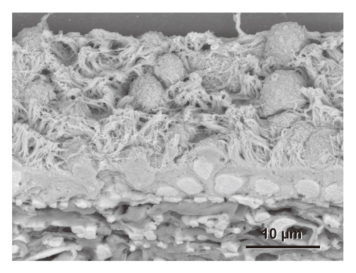
Fig. 7 Rat bronchioles fixed using 10 % formalin solution(4 % paraformaldehyde alone), which is typically used to fix histopathology specimens for light microscopy. The micrograph clearly shows the elaborate architecture of the ciliated epithelium(top) and collagen fibers with a crisscrossed, layered structure(bottom). Section thickness: 20 μm.
Correlative light and electron microscopy(CLEM) is a technique for improving the scientific accuracy of electron micrographs. CLEM combines optical and electron microscopy to produce images with electron-microscopy resolution so that instead of “missing the forest for the trees”, users are able to “observe the forest, select a tree, and then examine its leaves”. Figure 8 shows a rat renal corpuscle sample treated with our protocol and imaged with CLEM. To produce this image, a sample stained with hematoxylin and eosin was observed under a light microscope, and then the cover slip was removed to expose the sample, which was stained using potassium permanganate and lead and then observed using low-vacuum scanning electron microscopy. The protrusions of the podocytes seen with light microscopy(arrow) are imaged at a resolution not possible with light microscopy, allowing the fine-grained structure to be observed.
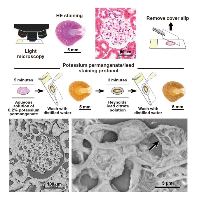
Fig. 8 Micrographs of rat renal corpuscle imaged with CLEM. The sample was first stained with hematoxylin and eosin and observed using light microscopy. The cover slip was then removed, and the sample was stained with potassium permanganate/lead and observed using low-vacuum scanning electron microscopy. The area observed with light microscopy is seen in elaborate detail. The protrusions of the podocytes seen with light microscopy(arrow) are imaged at a resolution not possible with light microscopy, revealing the fine-grained structure.
When the TM4000PlusII is used, real-time images of a section obtained by the CCD camera in the instrument show the area to be observed at electron-microscopy resolution. This handy standard feature greatly simplifies CLEM(Figure 9). With this tool, users can “observe a section, select a tissue region, and then examine its cells” just as in the “observe the forest, select a tree, and then examine its leaves” idiom mentioned above.
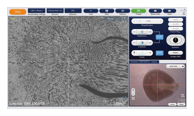
Fig. 9 Operating screen for TM4000PlusII. Real-time images of a section obtained by the CCD camera in the instrument(lower right) show the area to be observed at electron-microscopy resolution(left). This handy standard feature greatly simplifies CLEM.
Our protocol can be used to image, at electron-microscopy resolution, the three-dimensional structure of adhesive cells cultured on a light microscope slide. The micrographs of the SUIT-2 pancreatic cancer cell line shown in Figure 10 clearly show the intricate adhesions and connections between cells not visible at light-microscopy resolution.
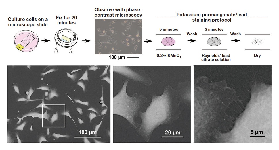
Fig. 10 Micrographs of cultured cells(SUIT-2 pancreatic cancer cell line). Once the best area for observation is selected using phase contrast microscopy, potassium permanganate/lead staining is performed, and the specimen is observed using low-vacuum scanning electron microscopy. The micrographs show the intricate adhesions and connections between cells not visible at light-microscopy resolution.
This article has described a new electronic staining technique that does not require uranium compounds. As stated at the beginning of the article, these compounds have long been a problematic but necessary component in staining. With the proposed protocol for conveniently and rapidly imaging the detailed architecture of the cells and tissues that make up the organs of the body at electron-microscopy resolution, tabletop low-vacuum scanning electron microscopes are finding new biomedical and clinical applications such as the histopathological diagnosis of tissue and evaluation of the morphological quality of regenerated organs.
References
See more
