
3. Principle and System Configuration of HPLC (3)
Configuration of an HPLC system
An HPLC system consists of a pumping unit, sample-injection unit, separation unit, detection unit, and data-processing unit. Each of these units is essential for performing the analysis.
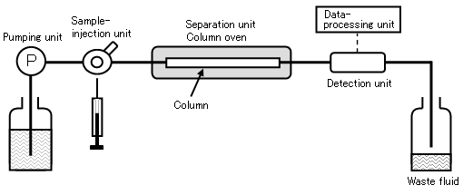
Pumping unit
It is necessary to pump the eluent at a constant flow rate and pressure.
Conventional, analytical HPLC pumps are the most common type, but semi-micro and a preparative pumps are also used depending on the range of the eluent flow rate required.
The pump is selected to suit the purpose of the analysis.
Analyses were first performed using isocratic separations in which the eluent
composition remains unchanged during the analysis. This techniques is adequate for simple
separations. When a sample contains many components, such as a sample for amino-acid analysis is
analyzed, it is very difficult to separate all of the components effectively using only one
eluent.
A gradient analysis allows the composition of the eluent to be changed during the
analysis. This often indicates that the concentration gradient is to be generated in a linear
manner. However, if the eluent composition is changed in a stepwise fashion, this is called a
step gradient.
[Gradient mixing methods]
Two mixing methods are available:
low-pressure and high-pressure.
Low-pressure mixing method:
The eluent to be absorbed is switched via electromagnetic valves. One pump is used for mixing.
System price is lower.
Up to four eluents can be mixed.
High-pressure mixing method:
Two pumps are used. The eluents are mixed after pumping. The response of the gradient is superior because of the small volume from the mixing unit to the column. System price is higher due to the increase in the number of pumps.
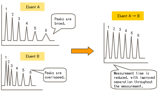
Figure 2 illustrates the merits of gradient analysis.
If eluent A is used, the components eluted earlier are clearly separated, but the components eluted later show broad peaks or may not elute from the column.
In contrast, if eluent B is used, the former are insufficiently separated, while the latter show sharp peaks.
In this case, a gradient analysis in which the eluent composition is changed from the A to B during the analysis can be used to improve the separation over time.
Sample-injection unit
A sample is injected into the flow path for analysis.
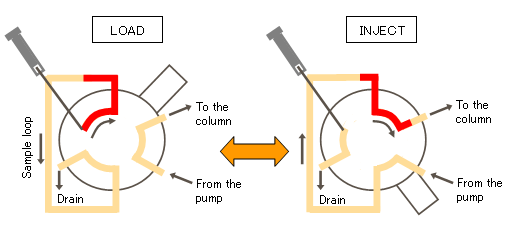
This is accomplished via a manual injector or an autosampler. Each type is equipped with six-port valves, so that a sample can be injected into the flow path at continuous pressure. For the manual injector, the knob is manually operated to deliver the sample to the column, as shown in Figure 3.
- The knob is set at the "LOAD" position for sample injection, as shown in the left image. Using a microsyringe, the sample can be injected into the sample loop, which is separated from the flow path.
- The knob is turned to the "INJECT" position. The eluent travels through the loop from the pump then delivers the sample to the column. The autosampler can perform similar work automatically, enabling unmanned continuous operation.
Separation unit
A column is selected to suit both the sample and the purpose of separation. The column oven is used to maintain a constant column temperature. If the column temperature were allowed to vary during qualitative or quantitative analysis, the elution time of the components would change, so that an accurate analysis could not be performed. An analysis temperature between 25 and 50°C is often selected.
Detection unit
The components eluted from the column are detected, and the detection data are converted into an electrical signal. The detector is selected to suit the sample.
Table 1. Major types of detector
| UV detector | The light source is a D2 lamp. This detector is used mainly to detect components having an absorption wavelength of 400 nm or less in the ultraviolet region. |
|---|---|
| UV-VIS detector | A D2 lamp and a W lamp are used as the light source. This detector is effective in the detection of coloring components such as dyes and stains because of coverage of the visible light region. |
| Diode array detector (DAD) | Data on the spectrum from the ultraviolet to visible light range is also collected. |
| Fluorescence (FL) detector | Fluorescent substances can be detected specifically with high sensitivity. |
| Differential refractive index (RI) detector | Change in the refractive index is detected. Components absorbing no ultraviolet light can also be detected despite low sensitivity. |
| Conductivity detector | Mainly inorganic ions are detected by monitoring the conductivity. |
The electrochemical detector (ECD), evaporative light scattering detector (ELSD), Corona® Charged Aerosol Detector (CAD), and others are also used. In addition, the LC-MS system, in which the components separated by HPLC are further analyzed using a mass spectrophotometers, is becoming widely used because of its high sensitivity and the possibility of specific detection.
Data-processing unit
The concentration of each detected component is calculated from the area or height of the corresponding peak, and reported. Although previously, easy-to-use integrators were mainly used, systems in which a PC performs both the operation of the units and the analysis of the results have recently played a central role.
* CAD, Corona, Coulochem, CoulArray, Cat-a-Phase and ESA are registered trademarks ® of Dionex Corp.