

Ion Milling System IM4000II
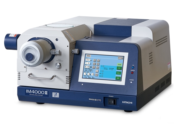
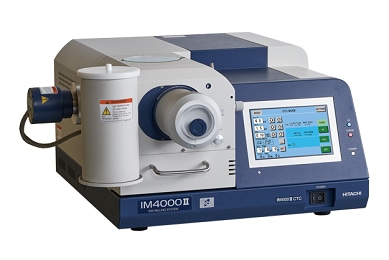
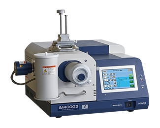
IM4000II supports both cross section milling and flat-milling to prepare specimens depending on the purpose. Cooling Temperature Control, Air Protection Holder Unit, and Various options enable preparation of various cross section specimens.
Features
High Milling Rate
The cross section milling rate*1 of the IM4000II is 500 µm/h or greater. It is effective for hard materials that conventionally require extended processing.
*1 The maximum milling depth in one hour for Si protruding 100 μm from the maskedge.
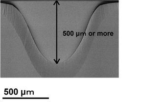
Specimen : Si wafer (2 mm thick)
Accelerating voltage : 6.0 kV (IM4000II)
Swing angle : ±30°
Milling time : 1 hour
When the swing angle during cross section milling changes, the corresponding processing width and depth change. The figure below shows the SEM images of a Si wafer after cross section milling. Processing conditions are the same as shown above except the swing angle has been reduced from ±30˚ to ±15˚. It is demonstrated that the processing depth is deeper than the above results and therefore very effective for rapid cross section preparation of specimens with a target structure far from the top surface.
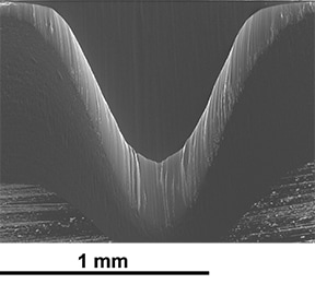
Specimen : Si wafer (2 mm thick)
Accelerating voltage : 6.0 kV (IM4000II), 8.0 kV (ArBlade 5000)
Swing angle : ±15°
Milling time : 1 hour
Hybrid Milling
Cross section Milling
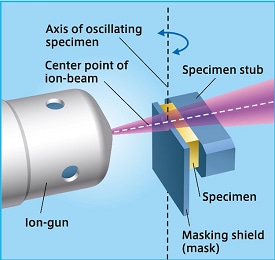
A pristine surface can be achieved by sputtering (milling) protruding parts of the specimen that extend beyond the maskedge. By irradiating the ion-beam parallel to the processed surface of the specimen, flat and smooth milling is possible even with complex materials of different compositions.
Main Uses
- Prepare a cross section specimen in a localized region of interest (ROI)
- Prepare a cross section specimen that is difficult to polish by other methods (composite materials, multi-layer interface, papers/films, etc.)
Flat-milling
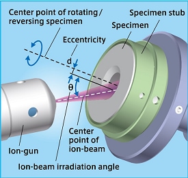
In flat-milling, a wider area can be processed than in cross section milling via eccentricity of the ion-beam and rotating specimen center points. It is also possible to emphasize or reduce irregularities by changing the irradiation angle of the ion-beam in order to reveal crystal orientation and/or subtle compositional differences.
Main Uses
- Remove mechanical artifacts from the polishing process (maximum diameter of 50 mm x thickness of 25 mm)
- Remove the surface or upper layers of multilayer film
- Discriminate layers of the cross section for multilayer film (emphasizing irregularities)
- Preprocess large areas for EBSD (reducing irregularities)
Options
Cooling Temperature Control*1
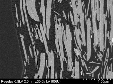
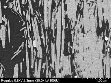
Sensitive specimens can be cooled with liquid nitrogen during processing. The cooling temperature control uses indirect cooling and maintains a temperature during processing in order to prevent phase transitions.
In the example below, specimen cooling suppresses thermal deformation in the heat-sensitive styrene-based latex, resulting in a smooth processed surface.
*1 Option to deliver with the main unit
Specimen: Functional material to reduce plastic usage (Made of paper)
Air Protection Holder Unit
The Air Protection Holder can be used to keep air-sensitive specimens (such as battery material) isolated from the environment. A specimen fabricated using the IM4000II can be loaded into a SEM and/or Atomic Force Microscope (AFM) without exposure to the outside environment. This function can be used in combination with the cooling temperature control (except a flat-milling holder).
*1 Compatible only with Hitachi High-Tech FE-SEM with air protection holder unit.
*2 Compatible only with Hitachi High-Tech AFM with vacuum.
Stereo Microscope Unit for Process Observation
A stereo microscope can be outfitted to observe the specimen during the milling process. Both binocularand trinocular-type systems are available. The trinocular version (as shown below) allows for view streaming to an external monitor when equipped with a CCD camera*1.
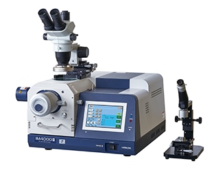
*1 CCD camera and monitor are not included.
Technical Explanation
Article information on Hitachi technical magazine "SI NEWS"
Specification
| Gas used | Ar (argon) gas |
|---|---|
| Ar gas flow control system | Mass flow controller |
| Accelerating voltage | 0.0 to 6.0 kV |
| Size | 616(W)×736(D)×312(H) mm |
| Mass | Main unit : 53 kg+Rotary pump : 30 kg |
| Maximum milling rate(Material : Si) | 500 μm/h*1 or more |
|---|---|
| Maximum specimen size | 20(W)×12(D)×7(H) mm |
| Specimen moving range | X±7 mm, Y 0 to +3 mm |
| Ion-beam intermittent irradiation | ON/OFF setting range 1sec to 59 min 59 sec |
| Swing angle | ±15°, ±30°, ±40° |
| Wide-area cross section milling | - |
*1 The maximum milling depth in one hour for Si protruding 100 μm from the maskedge.
| Maximum milling area | φ32 mm |
|---|---|
| Maximum specimen size | Φ50×25 (H) mm |
| Specimen moving range | ×0 to +5 mm |
| Ion-beam intermittent irradiation | ON/OFF setting range 1sec to 59 min 59 sec |
| Rotation speed | 1 rpm, 25 rpm |
| Swing angle | ±60°, ± 90° |
| Ion-beam irradiation angle | 0 to 90° |
Optional Specification
| Cooling temperature control*2 | Indirect cooling by LN2, Range of set temperature : 0 to -100 ℃ |
|---|---|
| Higher beam tolerance mask | 2× beam tolerance as compared to the standard mask (Cobalt-free) |
| Stereo microscope unit for monitoring the process | 15× to 100×, Binocular type, Trinocular type (correspond to CCD camera) |
*2 Option to deliver with the main unit. Some functions may be restricted during the use of cooling temperature control.
Citations
Article:The interplay between stack pressure, mechanical expansion and degradation pathways in lithium-ion batteries
(Nature Energy, June 29, 2026)
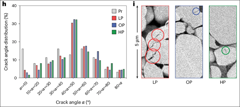
h). Distributions of the angle of cracks with the current collector extracted from cross-sectional SEM images of pristine (Pr) and cycled cathodes under HP (268 cycles), OP (374 cycles), and LP (374 cycles) conditions.
i). Cross-sectional SEM images of the representative cracks highlighted by colored circles in cycled cathodes under HP (268 cycles), OP (374 cycles), LP (374 cycles) conditions.
A better understanding of the influence of mechanical stress on lithium-ion batteries is vital because physical forces such as swelling and shrinking during charging cycles can cause cracking, loss of contact or short internal circuits. Any such investigation requires reliable approaches that can identify those cracking defects and guarantee them not resulting from either sample preparation or sample degradation induced by the environment.
Borad ion milling is the ideal sample preparation technique that allows for controlled and stress-free polishing of materials, and thus to generate high-quality cross sections with minimal artifacts. In addition, when air protection capability is integrated with ion milling & SEM tools, it prevents exposure of the sensitive lithium-ion batteries to both oxygen and humidity during the entire workflow ranging from sample loading to an ion milling system to the post-milling SEM inspection.
As illustrated in this paper, cross-section milling using a Hitachi ion milling system equipped with air protection function is utilized to ensure pristine cross sections of a battery electrode, in which unambiguous detection of original defects can be achieved readily. It proves that different degradation pathways occur outside the optimal pressure window. Low stack pressure accelerates cracking, whereas high pressure promotes lithium plating. Consequently, a straightforward strategy to extend battery lifespan can be developed via optimizing stack pressure and balancing degradation mechanisms.