Chaobin Zeng*1, Hiroaki Matsumoto*2, Keisuke Igarashi*2, Wenguang Lu*2, Kinshiro Sakamoto*3, Stas Dogel*4
The growing demand for understanding real structure-property relationships in gas-solid reaction processes (e.g., in catalysis) has accelerated the development of in-situ STEM/SEM/TEM techniques1,2). Conventional STEM/SEM/TEM requires a high vacuum (typically 10-5 to 10-6 Pa around the sample area), which is essential to minimize electron scattering by residual gases, protect sensitive filament, and prevent sample contamination. Introducing gases into the sample area thus requires specialized designs that balance vacuum integrity with environmental control.
For gas-solid reaction studies, two principal approaches are employed to introduce gases while combining with micro-electro-mechanical system (MEMS) heating. The first approach, known as the open-cell method, employs a dedicated environmental STEM/SEM/TEM with differential pumping systems to allow the direct introduction of gas into the sample region within the TEM column3). This approach enables gas-solid experiments within the column itself, offering benefits such as high signal-to-noise ratio imaging, secondary electron detection, efficient energy-dispersive X-ray spectroscopy (EDS) characterization, and low background in electron energy-loss spectroscopy(EELS). However, achievable gas pressure remains limited, typically ranging from ~10 Pa to 2000 Pa4,5), depending on the instrument.
The second approach employs a closed-cell holder, in which gas is confined between two thin SiNX membranes (typically 30–50 nm thick) to maintain high-pressure environments up to several bar—close to industrial reaction conditions6). While this enables higher pressures, it also results in significant electron beam scattering from the membranes and enclosed gas, leading to poor signal-to-noise ratio in imaging, elevated background noise in EELS, and blocked SE signals for surface/topological characterization. Although image contrast can be improved by increasing the probe current, this often introduces undesired beam-induced sample effects.
The investigation of gas-solid reactions (e.g., reduction, oxidation) through in-situ microscopy is constrained by a dual challenge: the limited pressure range in open-cell systems, the pronounced beam effects and low spectrum analysis efficiency in closed-cell systems. To address these constraints, advancing in-situ methodologies necessitates a focus on low radiation dose, high signal-to-noise imaging, and enhanced operational usability.
In this work, we introduce a semi-open gas injection system that supports in-situ gas-solid reactions at pressures up to 7 kPa, while maintaining high signal-to-noise ratios in concurrently acquired atomic-resolution annular darkfield(ADF), bright-field (BF), and secondary electron (SE) images. This approach effectively bridges the pressure gap of conventional open-cell designs without incurring the severe signal degradation characteristic of closed-cell environments.
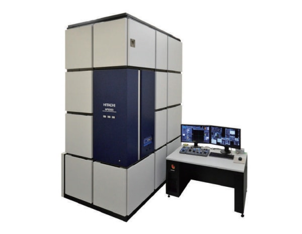
Hitachi’s field emission transmission electron microscope HF5000 is a 200 kV environmental scanning transmission electron microscope (E-STEM) featuring a cold field emission gun and probe Cs-corrector. It is equipped with an optimized orifice aperture in the condenser lens area and a differential pumping system (Fig. 1), enabling gas injection into the sample region via a nozzle positioned above the sample area between the pole pieces (Fig. 2). Although the maximum achievable gas pressure is relatively low (~10 Pa), this open gas injection design ensures efficient gas delivery to the sample surface. The injected gas flow effectively displaces adsorbed reactant species, thereby sustaining high reaction efficiency before being pumped away. Secondary electron signals are collected by a Thornley-Everhart detector located above the upper pole piece (Fig. 1) 7). Benefit from aberration corrector, in-situ SE imaging can achieve atomic resolution, providing detailed surface morphological information. This capability provides complementary information: SE imaging reveals surface morphology, while simultaneously acquired ADF and BF signals offer projected structural information from the sample8).
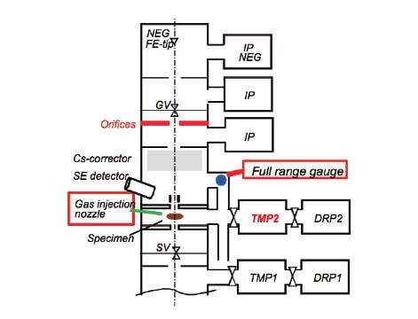
Fig. 1 Vacuum system of Hitachi HF5000
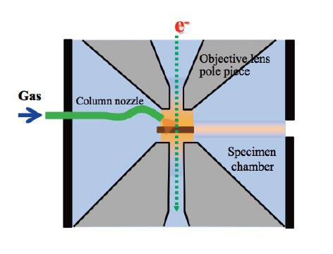
Fig. 2 Schematic of in-situ gas injection method in HF5000
The semi-open cell gas injection system is designed to integrate a closed-cell heating holder with the ESTEM (Hitachi HF5000). To simultaneously achieve a locally high gas pressure at the sample while preserving high-resolution imaging and spectroscopic capabilities, we designed a modified top chip featuring a central 90 μm × 90 μm aperture in the SiNX membrane (Manufactured by Norcada, Fig. 3). Gas is introduced through the holder body and is actively evacuated by the ESTEM’s differential pumping system. This apertured upper membrane functions as a secondary orifice within the overall in-situ setup. This configuration enables efficient delivery of high-pressure gas to the sample surface while allowing secondary electrons to escape through the aperture for detection by the SE detector. The gas control facility is integrated within HF5000 ESTEM system (Fig. 4). The gas delivery and control system is fully integrated into the Hitachi HF5000 ESTEM. Direct measurement of the local gas pressure in the sample region is experimentally challenging. Therefore, we performed a numerical simulation to estimate the pressure distribution based on the known gas flow rate, the specifications of the differential pumping system, and the geometry of the chip and holder assembly.
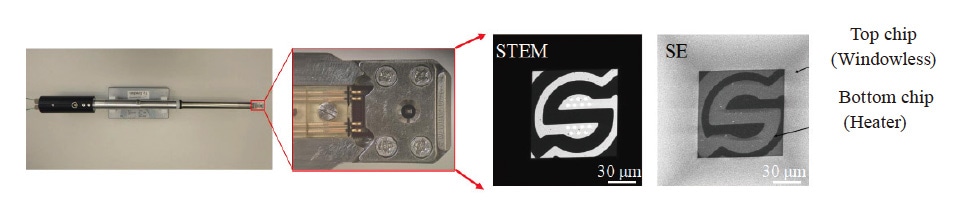
Fig. 3 Semi-open chip installed in in-situ holder
Figure 5 presents the simulated pressure profile in the sample vicinity. The x-axis represents the gas flow rate (in standard cubic centimeter per minute, sccm), and the y-axis corresponds to pressure. The blue data points denote the pressure recorded at the full-range gauge within the microscope column, while the green data points indicate the estimated local pressure at the sample position. The simulation results demonstrate that a local pressure of up to 7 kPa can be achieved at the sample with a gas flow rate of 3.5 sccm.
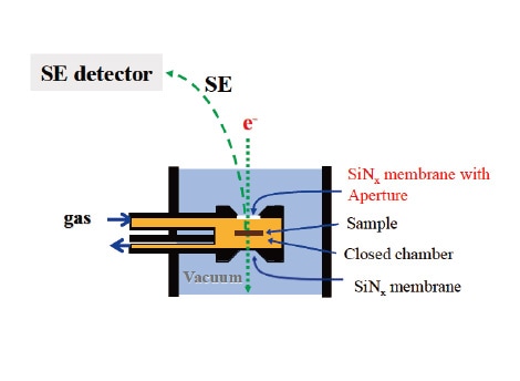
Fig. 4 Schematic of in-situ semi-open cell system
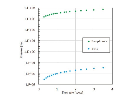
Fig. 5 Simulation of pressure around sample area
To validate the performance of the high-pressure semi-open cell in-situ heating system and to directly compare the pressure regimes achievable in open-cell and semi‑open cell configurations, we conducted two independent experimental studies. The first evaluated the system performance by monitoring the behavior of CeO2 nano-cubes under a H2 atmosphere at a maximum pressure of 7 kPa during heating to 700 °C. The second consisted of comparative in-situ reduction experiments on Fe2O3 nanoplates, performed under heating with varying H2 pressures in both open-cell and semi‑open cell configurations using the Hitachi HF5000 ESTEM.
The CeO2 nanocubes were dispersed on the bottom SiNX membrane of the semi-open cell system. Figure 6 presents atomic-resolution ADF, SEM, and BF images acquired along the [001] direction of CeO2 at 700 °C under 7 kPa H2. Despite the high-pressure gas environment, the images exhibit high signal-to-noise ratios at a probe current of 35 pA, a condition difficult to achieve in closed-cell systems under equivalent beam currents. Surface reconstruction structures of the CeO2 nano-cubes are clearly resolved in ADF, SEM, and BF.
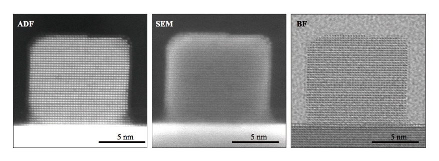
Fig. 6 Simultaneously images of ADF, SEM, BF at 700 °C with 7 kPa H2
During in-situ heating at 700 °C under 7 kPa H2, numerous small dark contrast features were observed on the CeO2 surface in both ADF and SE images. These features are attributed to oxygen vacancy-rich regions, as confirmed by line scan analysis across the corresponding areas. Ce M-edge EEL spectra (Fig. 7) reveal an increased Ce M5/M4 EELS ratio in these dark contrast regions, indicating a higher local concentration of Ce3+ resulting from reduction at elevated temperature9). This finding demonstrates that surface oxygen vacancies are preferentially enriched in these regions, and that such surface chemical heterogeneity can be effectively visualized using SE imaging.
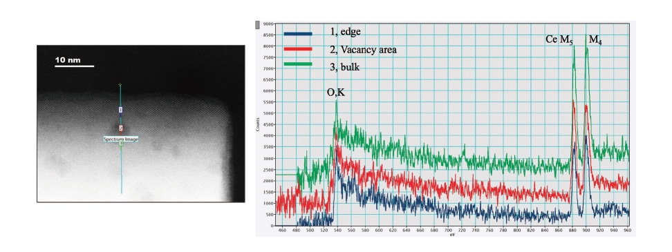
Fig. 7 EELS line scan of CeO2 after at 700 °C with 7 kPa H2
In-situ reduction of Fe2O3 in the TEM presents a significant challenge for the overall in-situ system, particularly with regard to system cleanliness, residual gas composition, pressure stability, and temperature control. In this study, we experimentally demonstrate the temperature gap between conventional open-cell and the proposed semi-open cell in-situ configurations under different H2 pressures.
Figure 8 shows the pristine Fe2O3 nanoplate, and Figure 9 presents the resulting nanoparticles after reduction at 1000 °C under 10 Pa H2 using the open-cell configuration. The Fe2O3 nanoplate was completely reduced and transformed into Fe nanoparticles exhibiting a Wulff-constructed morphology10). Complete reduction was further confirmed by EELS analysis, which revealed the absence of the O K-edge in the reduced sample. These results demonstrate that Fe2O3 can be fully reduced at 1000 °C under 10 Pa H2 in an open-cell system.
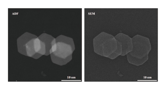
Fig. 8 ADF and SEM image of Fe2O3 nanoplate
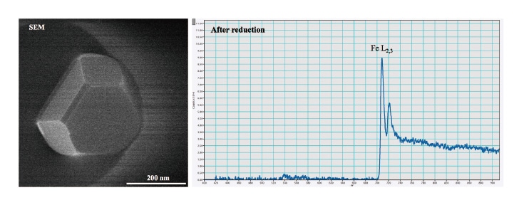
Fig. 9 EELS spectrum analysis of Fe2O3 nanoplate and reduced Fe nanoparticle at 650 °C with 5000 Pa H2
Compared to the open-cell configuration, the semi-open system enabled the reduction of Fe2O3 nanoplates at 480 °C under 5000 Pa H2. This reduction was confirmed by a decrease in particle size, morphological evolution toward a Wulff-constructed structure—similar to that observed in the open-cell system at 1000 °C under 10 Pa H2—and a marked increase in ADF image contrast (Fig. 10). By increasing the H2 pressure from 10 Pa to 5000 Pa, the reduction temperature was significantly lowered from 1000 °C to 480 °C. During the reduction process, surface reconstruction was observed on the Fe2O3 nanoplates, characterized by atomic migration across the surface (Fig. 11).
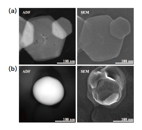
Fig. 10 ADF and SEM images of before (a) and after (b) reduced Fe nanoparticle at 480 °C with 5000 Pa H2
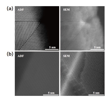
Fig. 11 Fe2O3 surface reconstruction at 300 °C (a) and 420 °C (b) with 5000 Pa H2
Based on the environmental HF5000 platform, we developed a semi-open gas injection system by modifying the top chip of a conventional closed gas cell with an aperture structure. This design enables secondary electron detection under elevated gas pressures while preserving atomic-resolution STEM imaging capabilities. By integrating the differential pumping system of the environmental TEM with semi-open cell holder, we achieved simultaneous atomic-resolution STEM and SE imaging at 7 kPa using a 200 kV Cs-corrected environmental STEM/SE system (Hitachi HF5000). This approach effectively bridges the pressure gap between low-pressure and high-pressure gas-solid in-situ experiments.
Acknowledgements
We are grateful to Professor Yan Zhou of the Dalian Institute of Chemical Physics for providing the specimens used in this study and fruitful discussions of in-situ results. We also thank Norcada for chip manufacturing.
References
About the authors
*1 Chaobin Zeng
EM Application Group, Hitachi High-Tech Scientific Solutions (Beijing) Co., Ltd, Shanghai, China
*2 Hiroaki Matsumoto, Keisuke Igarashi, Wenguang Lu
Beam Technology & Analytical Systems Product Division, Core Technology & Solutions Business Group, Hitachi High-Tech Corporation
*3 Kinshiro Sakamoto
Product Development Digital Engineering Center, Design Strategy Division, Manufacturing & Technology Business Group, Hitachi High-Tech Corporation
*4 Stas Dogel
NAPG Director, Hitachi High-Tech Canada, Inc.
登録記事数 203件
まだまだあります。